5. Camera with Configurable View Volume
This renderer modifies the Camera class to give us more control over the
renderer's virtual camera.
In the previous renderers, the camera is fixed at the origin, looking down the negative z-axis and has a fixed view volume (either a fixed projective view volume or a fixed orthographic view volume). This is not very convenient. In order to render a complex scene, we have to position each object relative to the (fixed) camera. It would be better to have the camera act like a real movie camera, where objects are positioned in a scene and then the camera is positioned in whatever location seems best. In fact, we should be able to move the camera around the scene, independently of moving the objects in the scene. In addition, a real movie camera can zoom in and out to view less or more of the objects in the scene.
In this renderer we give the Camera class the ability to set the camera's
view volume. This gives us two abilities that we did not have before. It lets
us set the aspect ratio of the camera's view rectangle. And it lets us "zoom"
the camera in and out of a scene.
In the next renderer we will allow the camera to translate in space and in a later renderer we will allow the camera to rotate in space and point in any direction.
5.1 Renderer source code
The Java source code for this renderer is publicly available as a zip file.
Here is a link to the renderer's source code.
Download and unzip the source code to any convenient location in your computer's file system. The renderer does not have any dependencies other than the Java 11 (or later) JDK. Once you have downloaded and unzipped the distribution, you are ready to compile the renderer and run the renderer's (interactive) example programs.
In the previous renderer the first pipeline stage was Model2Camera. This
renderer splits that stage into two stages, Model2View and View2Camera.
This renderer has one new file in the pipeline package,
View2Camera.java,
and the previous Model2Camera.java pipeline stage is renamed
Model2View.java.
The files Pipeline.java and Pipeline2.java are modified to put the
new View2Camera stage into the rendering pipeline after the Model2View
stage.
In the scene package, the file
Camera.java
is updated to hold the camera's view volume parameters.
The client programs are modified to make use of the camera's view volume feature.
5.2 Pipeline
The pipeline has the following seven stages.
       v_0 ... v_n     A Model's list of Vertex objects
          \   /
           \ /
            |
            | model coordinates (of v_0 ... v_n)
            |
        +-------+
        |       |
        |   P1  |    Model-to-view transformation (of the vertices)
        |       |
        +-------+
            |
            | view coordinates (of v_0 ... v_n) relative to an arbitrary view volume
            |
        +-------+
        |       |
        |   P2  |    View-to-camera (normalization) transformation (of the vertices)
        |       |
        +-------+
            |
            | camera coordinates (of v_0 ... v_n) relative to the standard view volume
            |
           / \
          /   \
         /     \
        |   P3  |   Near Plane Clipping (of each primitive)
         \     /
          \   /
           \ /
            |
            | camera coordinates (of the near-clipped v_0 ... v_n)
            |
        +-------+
        |       |
        |   P4  |    Projection transformation (of the vertices)
        |       |
        +-------+
            |
            | image plane coordinates (of v_0 ... v_n)
            |
           / \
          /   \
         /     \
        |   P5  |   Clipping (of each primitive)
         \     /
          \   /
           \ /
            |
            | image plane coordinates (of the clipped vertices)
            |
        +-------+
        |       |
        |   P6  |    Viewport transformation (of the clipped vertices)
        |       |
        +-------+
            |
            | pixel-plane coordinates (of the clipped vertices)
            |
           / \
          /   \
         /     \
        |   P7  |   Rasterization & anti-aliasing (of each clipped primitive)
         \     /
          \   /
           \ /
            |
            |  shaded pixels (for each clipped, anti-aliased primitive)
            |
           \|/
    FrameBuffer.ViewPort
Exercise: Rewrite Pipeline.java so that the normalization pipeline
stage, View2Camera, comes after the Projection pipeline stage.
5.3 View Volumes
Recall that the renderer has two view volume shapes. One shape for perspective projection and one shape for orthographic projection.
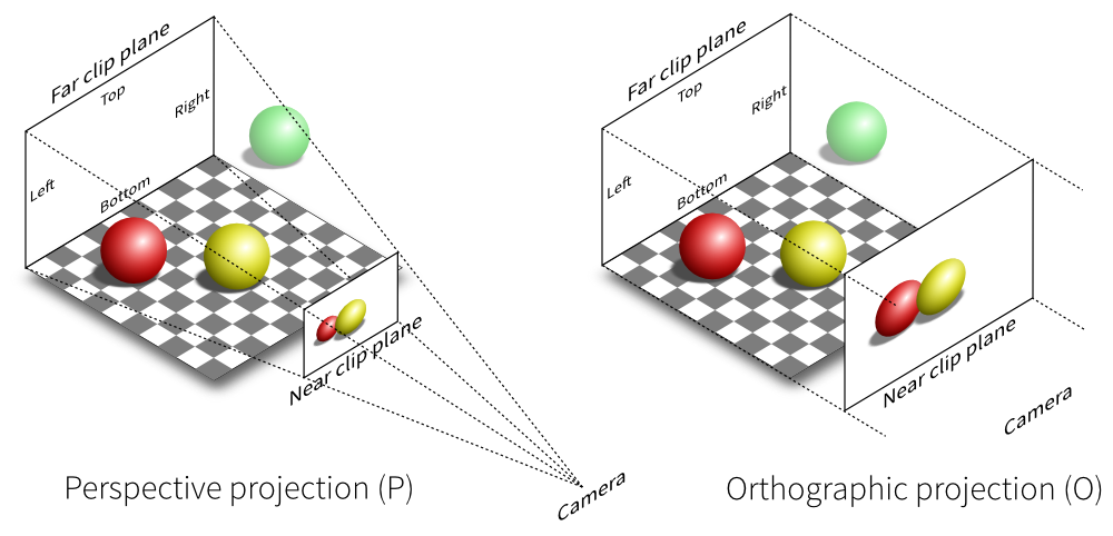
In the previous renderers these view volumes were fixed. This renderer allows us to change the shape of each view volume.
The perspective view volume is determined by four slanting planes. The
orthographic view volume is determined by four planes parallel to the
coordinate planes. These planes are all determined by the rectangle where
the view volume intersects the image-plane, z = -1. In this renderer we
change the shape of a view volume by changing the edges of that rectangle.
In this renderer the view volume for a Camera object is determined by four
parameters,
left,right,bottom,top.
These four parameters represent the four edges of the rectangle where the
view volume intersects the image-plane. The left and right parameters
are coordinates on the x-axis. The top and bottom parameters are
coordinates on the y-axis.
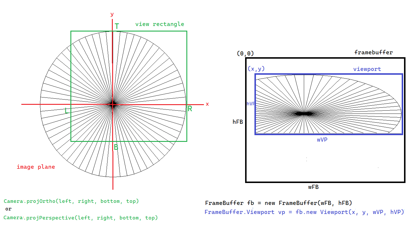
The intersection of the view volume with the image-plane is called the
view rectangle of the Camera.
For the perspective projection, the view volume is an infinitely long frustum
that is formed from the pyramid with its apex at the origin and its base in
the plane z = -1 with edges x = left, x = right, y = bottom, and
y = top.
For the orthographic projection, the view volume is an infinitely long
parallelepiped that is formed from the rectangle in the z = -1 plane with
edges x = left, x = right, y = bottom, and y = top.
Here are some online demo programs that let you play with the shape of a camera's view volume.
- https://webgl2fundamentals.org/webgl/frustum-diagram.html
- https://webgl2fundamentals.org/webgl/webgl-visualize-camera-with-frustum.html
- https://webgl2fundamentals.org/webgl/webgl-visualize-camera-with-orthographic.html
- https://cs.wellesley.edu/~cs307/threejs/demos-s21-r95/Camera/camera-api.shtml
- https://cs.wellesley.edu/~cs307/threejs/demos-s21-r95/Camera/frustum.shtml
- https://www.songho.ca/opengl/gl_transform.html#example2
The Camera class has static factory methods for constructing Camera
objects of the appropriate type and shape.
    public static Camera projPerspective(final double left,
                                         final double right,
                                         final double bottom,
                                         final double top)

    public static Camera projOrtho(final double left,
                                   final double right,
                                   final double bottom,
                                   final double top)
If you look in the code for the Camera class you will see that it has
only one constructor and that constructor is private. A private
constructor can only be called by code within the class file. Any external
code that wants to construct a Camera object cannot call the Camera
constructor. Code external to the Camera class must call one of the
static factory methods in the Camera class. A static factory method
is another object-oriented design pattern. Static factory methods are more
versatile than traditional constructors. They solve many problems that
often come up when using constructors. Many modern Java designs emphasize
static factory methods over constructors.
- https://en.wikipedia.org/wiki/Factory_method_pattern
- https://www.baeldung.com/java-constructors-vs-static-factory-methods
5.3.1 Normalized View Volumes
In the previous renderers the camera used fixed view volumes, one for perspective projection and another for orthographic projection.
The fixed perspective view volume was the infinitely long pyramid formed from the pyramid with its apex at the origin and its base in the plane z = -1 with edges x = -1, x = +1, y = -1, and y = +1.
The fixed orthographic view volume was the infinitely long parallelepiped formed from the square in the plane z = 0 with edges x = -1, x = +1, y = -1, and y = +1.
In other words, the two fixed view volumes both had the parameter values
top = right = 1 and bottom = left = -1.
These two fixed view volumes are still important. We call them the normalized view volumes (or sometimes the "standard view volumes").
The normalized view volumes are important because the View2camera.java
pipeline stage transforms a camera's arbitrary view volume into a standard
view volume. Then, all the following pipeline stages do their work in the
normalized view volume, just as they did in the previous renderers. This
design means that this change in a camera's view volume does not have
any effect on the later pipeline stages.
5.4 Aspect Ratio
You probably have noticed that many of the screens that you look at have slightly different "shapes". Some are more square (old TVs and old CRT monitors) and some are more rectangular. Some of the rectangular screens are looked at with their long edge horizontal (movie screens and laptop screens) and some are looked at with their long edge vertical (tablets and smart phones). This shape of a screen is called the screen's "aspect ratio".
The aspect ratio of a rectangle is defined as the ratio of its horizontal length to its vertical length (or, width/height). We define the aspect ratio of a screen to be the ratio of its horizontal length to its vertical length, both measured in pixels.
We will define the aspect ratio of a view volume to be the aspect ratio of its view rectangle (in the camera's view-plane, z = -1).
For both perspective and orthographic projection, the aspect ratio of the view volume's view rectangle is
                   right - left      width
   aspect ratio = --------------- =  ------
                   top - bottom      height
Notice that a square screen has an aspect ration of 1. A rectangular screen with its long edge horizontal has an aspect ratio > 1. A rectangular screen with its long edge vertical has an aspect ratio < 1.
An aspect ratio > 1 is called landscape mode. An aspect ratio < 1 is called portrait mode.
         aspect ratio > 1               aspect ratio < 1
           (landscape)                     (portrait)
     +----------------------+            +------------+
     |                      |            |            |
     |                      |            |            |
     |                      |            |            |
     |                      |            |            |
     +----------------------+            |            |
                                         |            |
                                         |            |
                                         |            |
                                         +------------+
Some devices, like tablets and smart phones, can easily switch between portrait and landscape modes. Other devices, like a movie screen, can't.
- https://en.wikipedia.org/wiki/Page_orientation
- https://en.wikipedia.org/wiki/Aspect_ratio
- https://en.wikipedia.org/wiki/Aspect_ratio_(image)
- https://en.wikipedia.org/wiki/Display_aspect_ratio
- https://en.wikipedia.org/wiki/Pixel_aspect_ratio
5.5 View2Camera Pipeline Stage
This renderer implements arbitrary view volumes with the View2Camera
pipeline stage. This pipeline stage defines a new coordinate system
and we need to derive the transformation formulas for this new
coordinate system.
5.5.1 View and Camera Coordinate Systems
In previous renderers, the clipping stage of the pipeline assumed that every
Vertex was in a coordinate system where the Camera had the standard view
volume. But in this renderer, we are assuming that every Vertex is in a
coordinate system where the Camera has the view volume determined by the
data in the Scene's Camera object. So the vertex data in our pipeline
is not in the coordinate system that our clipping stage expects.
We could rewrite the clipping stage to use the new view volumes, but we would
rather not do that (the clipping stage would need too many parameters, which
would just slow it down). So we use a trick. We define a new pipeline stage,
View2Camera.java, that transforms the coordinates of every Vertex from the
coordinate system of the camera's (arbitrary) view volume to the coordinate
system of the standard view volume. Another way to put this is that the new
stage transforms the camera's arbitrary view volume into the normalized (or
standard) view volume.
After this transformation, the previous clipping stage works just as it did in the previous renderers. (NOTE: We could put the new transformation stage either before or after the projection stage. We put it before the projection stage because that is where it needs to be in future renderers.)
We call the coordinate system relative to the camera's view volume the view coordinate system. We call the coordinate system relative to the standard view volume the camera coordinate system. So the new pipeline stage converts vertices from view to camera coordinates.
5.5.2 View2Camera Transformation
Here is a brief description of the formulas that transform an arbitrary perspective view volume into the normalized perspective view volume (and transform view coordinates into camera coordinates). We use two steps to transform the camera's arbitrary perspective view volume into the normalized perspective view volume. The first step "skews" (or "shears") the arbitrary view volume so that its centerline is the negative z-axis (that is, we skew an asymmetric view volume into a symmetric one). The second step scales the skewed view volume so that it intersects the plane z = -1 with corners (-1, -1, -1) and (+1, +1, -1) (that is, we scale the symmetric view volume so that it has a 90 degree field-of-view and becomes the normalized view volume).
Let R, L, t, b denote the right, left, top, and bottom fields
of the Camera. These numbers do not have to define a symmetric view volume.
We are not assuming that R = -L, or t = -b.
Let v = (x_v, y_v, z_v) be a vertex in view coordinates. Skew the perspective
view volume in each of the x and y directions so that the negative z-axis is the
centerline of the transformed view volume.
      x' = x_v - z_v * (R + L)/(2 * near)
      y' = y_v - z_v * (t + b)/(2 * near)
      z' = z_v
Next, scale the skewed view volume in each of the x and y directions so that it intersects the image plane z = -1 with corners (-1, -1, -1) and (+1, +1, -1).
      x_c = (2 * near)/(R - L) * x'
      y_c = (2 * near)/(t - b) * y'
      z_c = z'
Here is a derivation of the above formulas for the x-coordinate (the derivation for the y-coordinate is similar). We need to skew the xz-plane of the arbitrary view volume in the x-direction so that the centerline of the arbitrary view volume skews to the negative z-axis. For some skew factor s, the skew equations are
      x' = x_v + s * z_v
      z' = z_v
The point (x_v, z_v) = ( (R + L)/2, -near) from the arbitrary view
volume's centerline should skew to the point (0, -near) on the
negative z-axis. So
0 = (R + L)/2 + s * -near
so
s = (R + L)/(2*near).
Using this skew factor, we can compute that the point (x_v, z_v) = (R, -near) from the arbitrary view volume skews to the point (x', z') = ((R - L)/2, -near) and the point (L, -near) skews to the symmetric point (-(R - L)/2, -near).
After skewing the arbitrary view volume, we need to scale the xz-plane of the new symmetric view volume in the x-direction so that it has a 90 degree field-of-view. For some scale factor s, the scaling equations are
      x_c = s * x'
      z_c = z'.
We know that the point (x', z') = ((R - L)/2, -near) should scale to the point (x_c, z_c) = (near, -near) so
near = s * (R - L)/2
so
s = 2*near/(R - L).
We have a similar set of equations for transforming an arbitrary orthographic view volume into the normalized orthographic view volume.
We use two steps to transform the camera's arbitrary orthographic view volume into the normalized orthographic view volume. The first step translates the arbitrary view volume so that its centerline is the z-axis. The second step scales the translated view volume so that it intersects the plane z = 0 with corners (-1, -1, 0) and (+1, +1, 0).
Let v = (x_v, y_v, z_v) be a vertex in view coordinates. Translate the
orthographic view volume in each of the x and y directions so that the
z-axis is the centerline of the translated view volume.
      x' = x_v - (R + L)/2
      y' = y_v - (t + b)/2
      z' = z_v
Next, scale the translated view volume in each of the x and y directions so that it intersects the plane z = 0 with corners (-1, -1, 0) and (1, 1, 0).
      x_c = (2 * x')/(R - L)
      y_c = (2 * y')/(t - b)
      z_c = z'
5.5.3 View2Camera vs. Viewport Transformations
The Viewport transformation is, in a way, the opposite of the
View2Camera transformation. The View2Camera transformation takes an
arbitrary view volume, and its arbitrarily shaped view rectangle, and
transforms them into the normalized view volume and view rectangle so that
the clipping stage can do its work in the standard view rectangle. Then
the Viewport transformation transforms the standard view rectangle into
an arbitrarily shaped logical viewport in the pixel-plane. If the aspect
ratio of the camera's view rectangle matches the aspect ratio of the
framebuffer's viewport, then the Viewport transformation will undo the
distortion caused by the View2Camera transformation.
Suppose we have a sphere positioned in camera space and the camera's view
rectangle is not a square. Then the View2camera transformation will distort
the sphere into an ellipsoid shape when the transformation transforms the
camera's non-square view rectangle into the normalized, square, view rectangle.
But, if the framebuffer's viewport has the same aspect ratio as the camera's
view rectangle, then the Viewport transformation will distort the ellipsoid
back into a sphere, undoing the distortion caused by the View2Camera
transformation.
If the aspect ratios of the camera's view rectangle and the framebuffer's
viewport are not equal to each other, then the distortions caused by the
View2Camera and Viewport transformations do not "cancel" each other
out. In that case, we are left with a distorted image in the framebuffer's
viewport. The next section is about dealing with this situation.
5.6 Mismatched Aspect Ratios
When the aspect ratios of the view volume's view rectangle and the framebuffer's viewport are not equal, one of three possible compromises must be made when rendering the contents of the view volume into the viewport.
-
The image in the viewport is a distorted representation of the scene in the view volume.
-
The aspect ratio of the viewport must be changed to match the aspect ratio of the view rectangle. Some part of the framebuffer will not be used (in film, this is called letterboxing).
-
The aspect ratio of the view rectangle must be changed to match the aspect ratio of the viewport. Some part of the scene from the view rectangle will not be drawn into the viewport (in film, this is called cropping).
Another way to put this is that when the aspect ratios are not equal:
-
we can draw all of the contents from the view rectangle using all of the space in the viewport, but the resulting image must be a distorted representation of what is in the view rectangle,
-
we can draw an undistorted representation of all of the contents of the view rectangle but on only part of the viewport (letterboxing),
-
we can use all of the viewport to draw an undistorted representation of just part of what's in the view rectangle (cropping).
Here is another way to describe what we can do when the aspect ratio of the viewport is not the same as the aspect ratio of the view rectangle.
-
Distort the contents of the view rectangle to match the aspect ratio of the viewport.
-
Find a sub-rectangle within the viewport that has the same aspect ratio as the view rectangle, and then display the whole view rectangle in that viewport sub-rectangle. In other words, letterbox the contents of the view rectangle in a sub-rectangle of the viewport. How you position the sub-rectangle within the viewport is entirely arbitrary. It is most often either centered in the viewport, or attached to one edge, or one corner, of the viewport.
-
Find a sub-rectangle within the view rectangle that has the same aspect ratio as the viewport and then display that sub-rectangle of the view rectangle in the viewport. In other words, crop the contents of the view rectangle so that what is left has the aspect ratio of the viewport. How you position the sub-rectangle within the view rectangle is entirely arbitrary. It is often chosen so that the most important content of the view rectangle is centered in the sub-rectangle. If the most important content of the view rectangle is moving around, the chosen sub-rectangle may need to move around also. In film, this is called pan and scan.
Choice 1 is more or less the default choice in most renderers. If the aspect ratios of the view rectangle and the viewport do not agree, then the renderer will do the distorting.
We make choice 2 by resizing (and possibly repositioning) the framebuffer's viewport, or by creating a new viewport within the previous viewport.
We make choice 3 by resizing (and possibly repositioning) the camera's view volume.
- https://en.wikipedia.org/wiki/Letterboxing_(filming)
- https://en.wikipedia.org/wiki/Cropping_(image)
- https://en.wikipedia.org/wiki/Pan_and_scan
- https://learn.microsoft.com/en-us/windows/win32/medfound/picture-aspect-ratio
5.7 Scale, Fit, Letterbox, Crop, Scroll
When a "source" rectangle (usually the camera's view rectangle) must be displayed within a "destination" rectangle (usually the framebuffer's view port), if the two rectangles do not have the same aspect ratio, then we must use one of these effects,
- distort,
- letterbox,
- crop.
That is, either the original image from the source is distorted into the destination rectangle, or part of the source is cropped off by the destination rectangle, or the source is letterboxed within the destination rectangle, so some of the destination rectangle is unused.
Let us carefully analyze how we implement these effects. When we map the source rectangle onto the destination rectangle, we will always preserve horizontal and vertical directions. That is, we always map horizontal lines to horizontal lines, and the same for vertical lines.
Consider a horizontal line from the source rectangle that goes across the rectangle from the left edge to the right edge. We will scale (or "stretch") this line into a horizontal line in the destination rectangle. If the destination line stretches from the left edge to the right edge of the destination rectangle, then we say that we fit the horizontal direction. If the destination line does not stretch entirely across the destination rectangle, then we say that we letterbox the horizontal direction. If some sub-interval of the source line is stretched across the destination rectangle from the left edge to the right edge, then we say that we crop the horizontal direction. If we are allowed to interactively choose the sub-interval of the source line that gets stretched across the destination rectangle, then we say that we scroll the horizontal direction.
These four ways to scale a direction from the source rectangle onto the destination rectangle are our building blocks for ways to display a source rectangle in a destination rectangle.
- Fit along the horizontal (or vertical) direction.
- Letterbox along the horizontal (or vertical) direction.
- Crop along the horizontal (or vertical) direction.
- Scroll (pan) along the horizontal (or vertical) direction.
What we do in the x-direction is independent of what we do in the y-direction. For example, we can fit along the x-axis while we crop along the y-axis. Or we can crop along the x-axis while we letterbox along the y-axis.
Since there are four choices we can make in each of two directions, there are a total of 16 possible ways we can display a source rectangle in a destination rectangle. Most of those choices will not make sense and will cause distortion in either the horizontal or vertical direction. More often than not, there are only a few (two or three) choices that make sense and look good.
Here are a variety of scenarios that can come up when we display a source rectangle in a destination rectangle.
Example 1. Portrait to landscape:
Suppose that the source rectangle on the left must be displayed in the destination rectangle on the right. In this case, if we fit along both the x and y directions, then we get distortion. To avoid distortion, we need to preserve the aspect ratio of the source rectangle. To preserve the source's aspect ratio, we can fit along the x-axis and crop (or scroll) along the y-axis. Or we can fit along the y-axis and letterbox along the x-axis. (Imagine picking up the rectangle on the left and trying to fit it into the rectangle on the right while preserving its aspect ratio. If you cover the whole destination rectangle, then you must cut off part of the top or bottom of the source. If you do not cut off any of the source, then you must squeeze it into the destination with some empty space left over on its right or left sides.)
     +-----------+
     |           |
     |           |          #=====================#
     |           |          #                     #
     |           |          #                     #
     |  source   |          #     destination     #
     |           |          #                     #
     |           |          #                     #
     |           |          #=====================#
     |           |             aspect ratio > 1
     +-----------+               (landscape)
    aspect ratio < 1
      (portrait)
Example 2. Landscape to portrait:
If we fit both the x and y directions, then we again get distortion. To preserve the aspect ratio of the source rectangle, we can fit along the x-axis and letterbox along the y-axis. Or we can fit along the y-axis and crop (or scroll) along the x-axis. (Imagine picking up the rectangle on the left and trying to fit it into the rectangle on the right while preserving its aspect ratio. If you cover the whole destination rectangle, then you must cut off part of the left or right sides of the source. If you do not cut off any of the source, then you must squeeze it into the destination with some empty space left over above or below it.)
                                    #===========#
                                    #           #
                                    #           #
     +-------------------+          #           #
     |                   |          #           #
     |      source       |          #destination#
     |                   |          #           #
     |                   |          #           #
     +-------------------+          #           #
       aspect ratio > 1             #           #
         (landscape)                #===========#
                                   aspect ratio < 1
                                     (portrait)
Example 3. Both landscape:
In the case of a larger landscape aspect ratio displayed to a smaller landscape aspect ratio, we can either fit along the y-axis and crop (or scroll) along the x-axis, or fit along the x-axis and letterbox along the y-axis.
    +--------------------------------+          #=======================#
    |                                |          #                       #
    |                                |          #                       #
    |            source              |          #      destination      #
    |                                |          #                       #
    |                                |          #                       #
    +--------------------------------+          #=======================#
             aspect ratio >> 1                       aspect ratio > 1
               (landscape)                             (landscape)
In the case of a smaller landscape aspect ratio displayed in a larger landscape aspect ratio, we can either fit along the y-axis and letterbox along the x-axis, or fit along the x-axis and crop (or scroll) along the y-axis.
    +-----------------------+          #================================#
    |                       |          #                                #
    |                       |          #                                #
    |        source         |          #          destination           #
    |                       |          #                                #
    |                       |          #                                #
    +-----------------------+          #================================#
        aspect ratio > 1                        aspect ratio >> 1
          (landscape)                             (landscape)
Example 4. Both portrait:
In the case of a larger portrait aspect ratio displayed in a smaller portrait aspect ratio, we can either fit along the x-axis and letterbox along the y-axis, or fit along the y-axis and crop (or scroll) along the x-axis.
                              #===========#
                              #           #
                              #           #
    +-----------+             #           #
    |           |             #           #
    |           |             #           #
    |           |             #           #
    |  source   |             #destination#
    |           |             #           #
    |           |             #           #
    |           |             #           #
    +-----------+             #           #
   aspect ratio < 1           #           #
     (portrait)               #           #
                              #===========#
                             aspect ratio << 1
                               (portrait)
In the case of a smaller portrait aspect ratio displayed in a larger portrait aspect ratio, we can either fit along the x-axis and crop (or scroll) along the y-axis, or fit along the y-axis and letterbox along the x-axis.
    +-----------+
    |           |
    |           |
    |           |              #===========#
    |           |              #           #
    |           |              #           #
    |           |              #           #
    |  source   |              #destination#
    |           |              #           #
    |           |              #           #
    |           |              #           #
    |           |              #===========#
    |           |             aspect ratio < 1
    |           |               (portrait)
    +-----------+
   aspect ratio << 1
     (portrait)
The API
In general, letterboxing an image into a FrameBuffer is done by either
setting the default Viewport using the
setViewport(int x, int y, int widthVP, int heightVP)
method in the FrameBuffer class, or by creating a new
Viewport using the
Viewport(int x, int y, int widthVP, int heightVP)
constructor in the Viewport class.
Cropping a source image is done by changing the camera's view rectangle using either the
projOrtho(double left, double right, double bottom, double top)
or the
projPerspective(double left, double right, double bottom, double top)
method in the Camera class.
In the folder
renderer_5/clients_r5/aspect_ratio_examples/
there are two illustrations that try to visualize the relationship between
cropping, letterboxing, and the parameters to the projOrtho() and
setViewport() methods,
Scaling an image is done automatically by the renderer when it maps the whole of the camera's view-rectangle onto the framebuffer's viewport. If the aspect ratios of the camera's view-rectangle and the framebuffer's viewport do not agree, then the renderer will distort the final image in the viewport. Most of the time, we want to make sure that the view rectangle and the viewport have the same aspect ratio so that we get scaling without distortion.
When we crop an image in an interactive program, we can give the user the
option to "scroll" the image. In other words, we can give the user the
choice of which part of the original image gets cropped off. Scrolling is
part of the Java GUI system, it is not part of the renderer or part of our
FrameBuffer or Viewport classes. To allow a user to scroll through a
cropped image, we need to use a scrolling GUI component from the Java GUI
system. Java has three components that can be used for scrolling, Scrollbar,
JScrolBar, JSlider. Each component gives us an integer value that depends
on the placement of its "slider button". We use that value to set the view
rectangle in the camera's image-plane. For example code, see the following
three programs.
renderer_5/clients_r5/aspect_ratio_examples/Circle_v5_PanAndScan_JScrollBar.javarenderer_5/clients_r5/aspect_ratio_examples/Circle_v5_PanAndScan_JSlider.javarenderer_5/clients_r5/aspect_ratio_examples/Circle_v5_PanAndScan_Scrollbar.java
There is a version using each of JSlider, JScrolBar, and Scrollbar
because the three components act differently when it comes to keyboard focus.
Play with all three of these programs and be sure to activate the scrolling
components using the keyboard's arrow keys and switching keyboard focus between
the components by using the Tab key.
- https://docs.oracle.com/en/java/javase/21/docs/api/java.desktop/javax/swing/JScrollBar.html
- https://docs.oracle.com/en/java/javase/21/docs/api/java.desktop/javax/swing/JSlider.html
- https://docs.oracle.com/en/java/javase/21/docs/api/java.desktop/java/awt/Scrollbar.html
5.8 Java's ComponentListener Interface
In order for our client programs to respond to the user changing the size
of the program's JFrame, we need to implement the ComponentListener
event handler interface, in particular, the componentResized() method.
To get a sense of what it is we need to do, let us do some experiments with JShell.
Open a command-prompt window and on the command-line start a JShell session.
> jshell
When the jshell prompt appears, copy-and-paste the following block of code
into the prompt. JShell allows you to copy several lines of code at a time.
It will execute each line of code and then give you another prompt.
import java.awt.*
import javax.swing.*
var jf = new JFrame("Re-size Me")
var jpCenter = new JPanel()
var jpNorth  = new JPanel()
var jpEast   = new JPanel()
jpCenter.setBackground(Color.red)
jpNorth.setBackground(Color.yellow)
jpEast.setBackground(Color.green)
jf.add(jpCenter, BorderLayout.CENTER)
jf.add(jpNorth, BorderLayout.NORTH)
jf.add(jpEast, BorderLayout.EAST)
jf.pack()
jf.setSize(400, 400)
jf.setDefaultCloseOperation(JFrame.EXIT_ON_CLOSE)
jf.setVisible(true)
This code creates a JFrame object containing three JPanel objects.
By default, a JFrame uses the BorderLayout layout manager.
- https://docs.oracle.com/javase/tutorial/uiswing/layout/visual.html#border
- https://docs.oracle.com/javase/8/docs/api/java/awt/BorderLayout.html
A BorderLayout divides the JFrame into five regions. In this example
we are using three of them. We give each JPanel a distinct color so
that we can see it.
Resize the JFrame and watch how each JPanel gets resized by the layout
manager. Notice that the center JPanel gets most of the area from the
JFrame.
Define a simple ComponentListener object that overrides just the
componentResized() method. Add that listener to the JFrame (later
we will also add it to each JPanel). Copy-and-paste the following code
into your jshell prompt.
import java.awt.event.*
var resizeHandler = new ComponentAdapter(){
   @Override public void componentResized(ComponentEvent e){
      System.out.println(e + "\n");
   }
}
jf.addComponentListener(resizeHandler)
Resize the JFrame and look at the output in the console window. The
ComponentEvent objects tell you the location and size of the JFrame
after every resize event. Place the JFrame near the upper left-hand
corner of your computer's screen and then resize the JFrame. Place
the JFrame near the lower right-hand corner of your computer screen
and then resize the JFrame again.
Now add the listener object to each JPanel object. Do this one JPanel
at a time. Resize the JFrame (after adding the listener to each JPanel)
and notice the ComponentEvent objects that come from each panel (you
can tell them apart by their locations and sizes).
jpCenter.addComponentListener(resizeHandler)
jpNorth.addComponentListener(resizeHandler)
jpEast.addComponentListener(resizeHandler)
We can cause more controlled resize events by calling the setSize()
method on the JFrame. Type these commands into the jshell prompt,
one at a time. Notice that the center JPanel gets both horizontal
and vertical resize events. The north JPanel only gets the horizontal
resize events. The east JPanel only gets the vertical resize events.
jf.setSize(200, 200)
jf.setSize(201, 200)
jf.setSize(201, 201)
jf.setSize(205, 205)
Try directly resizing the center JPanel.
jpCenter.setSize(500, 500)
The JPanel did resize, but the JFrame did not.
If we pack() the JFrame we do not get what we might expect.
jf.pack()
Try giving the center JPanel a minimum size.
jpCenter.setMinimumSize(new Dimension(300, 300))
jf.pack()
Try giving the center JPanel a preferred size.
jpCenter.setPreferredSize(new Dimension(300, 300))
jf.pack()
Try changing the size of the center JPanel again.
jpCenter.setSize(500, 500)
jpCenter.setSize(30, 30)
jpCenter.setSize(300, 300)
jf.pack()
Add a component to each of the north and east JPanel so that they need
more than the bare minimum of area.
jpNorth.add(new JCheckBox("Check Me"))
jpEast.add(new JButton("Press Me"))
jf.pack()
Try the following command. Do you see the negative dimensions in the components?
jf.setSize(50, 50)
Restore the GUI to its "preferred" dimensions.
jf.pack()
If you haven't done so already, unzip the renderer_5.zip distribution.
Open a command-prompt window in the renderer_5 folder. From the command-line
run the build scripts to build the renderer_5.jar file.
    > build_all_classes.cmd
    > build_jar_files.cmd
    > clean_class_files.cmd
We shall use the jar file renderer_5.jar in JShell to create resizeable
GUIs that use the FrameBufferPanel class.
On the command-line (still in the renderer_5 folder) start a JShell
session. Test that JShell can use the renderer's jar file by typing the
following two lines of code. The first puts the renderer's jar file in
JShell's classpath. The second line should print out a small FrameBuffer
object.
    jshell> /env  --class-path ./renderer_5.jar
    jshell> new renderer.framebuffer.FrameBuffer(5, 5)
Copy-and-paste the following block of code into the jshell prompt.
import renderer.scene.*
import renderer.scene.primitives.*
import renderer.models_L.*
import renderer.pipeline.*
import renderer.framebuffer.*
import java.awt.*
import java.awt.event.*
import javax.swing.*
import javax.swing.event.*
var jf = new JFrame("FrameBufferPanel")
var jpNorth  = new JPanel()
var jpEast   = new JPanel()
jpNorth.setBackground(Color.yellow)
jpEast.setBackground(Color.green)
var fbp = new FrameBufferPanel(400, 400, Color.cyan)
jf.add(fbp, BorderLayout.CENTER)
jf.add(jpNorth, BorderLayout.NORTH)
jf.add(jpEast, BorderLayout.EAST)
jf.pack()
jf.setDefaultCloseOperation(JFrame.EXIT_ON_CLOSE);
jf.setVisible(true)
var resizeHandler = new ComponentAdapter(){
   @Override public void componentResized(ComponentEvent e){
      System.out.println(e + "\n");
   }
}
jf.addComponentListener(resizeHandler)
fbp.addComponentListener(resizeHandler)
Resize the JFrame several times. Notice from the ComponentEvent objects
in the console window that the FrameBufferPanel object gets resized by the
layout manager, but the FrameBuffer object in the FrameBufferPanel is not
being resized. Try this code.
fbp.getSize()
fbp.getFrameBuffer().getWidthFB()
fbp.getFrameBuffer().getHeightFB()
Here s a way to think about this. We have a nested configuration where a
JFrame window contains a FrameBufferPanel which contains a FrameBuffer.
    JFrame (resized by user)
    |
    \---FrameBufferPanel (resized by layout manager)
        |
        \---FrameBuffer  (not being resized)
The JFrame window gets resized by a user. The JFrame's layout manager
tells the nested FrameBufferPanel how it should resize itself. But nothing
(yet) is resizing the FrameBuffer nested inside of the FrameBufferPanel.
The ComponentListener object attached to the FrameBufferPanel does not
(yet) make the FrameBufferPanel resize its FrameBuffer. But a FrameBuffer
does not have a resize method. The dimensions of a FrameBuffer object are
final and immutable. In order for a FrameBufferPanel to "resize" its
FrameBuffer object, the FrameBufferPanel must instantiate a new
FrameBuffer object with the desired size.
Here is a ComponentListener object for the FrameBufferpanel that responds
to resize events by replacing the FrameBuffer with a new FrameBuffer that
fills the resized FrameBufferpanel.
var fbpResizeHandler0 = new ComponentAdapter(){
   @Override public void componentResized(ComponentEvent e){
      System.out.println(e + "\n");
      var fb = new FrameBuffer(fbp.getWidth(),
                               fbp.getHeight(),
                               Color.cyan);
      fbp.setFrameBuffer(fb);
   }
}
Replace the previous ComponentListener object with this new one.
fbp.removeComponentListener(resizeHandler)
fbp.addComponentListener(fbpResizeHandler0)
Resize the JFrame several more times. Notice from the ComponentEvent objects
in the console window that the FrameBufferPanel object gets resized by the
layout manager, and the FrameBuffer object in the FrameBufferPanel gets
"resized" by the event handler.
fbp.getSize()
fbp.getFrameBuffer().getWidthFB()
fbp.getFrameBuffer().getHeightFB()
Exercise: Rewrite the fbpResizeHandler0 resize event handler so that
it creates a Viewport within the FrameBuffer. Give the Viewport the
background color orange. Have the Viewport be centered in the FrameBuffer
and occupy 80% of the horizontal width of the FrameBuffer and 80% of the
vertical height of the FrameBuffer.
Let us use the renderer to put some 3D geometry in the FrameBuffer. First,
create a Scene.
var scene = new Scene("fbp-scene")
var model = new Sphere(1.0)
renderer.scene.util.ModelShading.setColor(model, Color.red)
scene.addPosition(new Position(model, "p0",
                               new renderer.scene.Vector(0, 0, -1.5)))
We need a resize event handler that renders this Scene into the
FrameBuffer in the FrameBufferPanel.
var fbpResizeHandler1 = new ComponentAdapter(){
   @Override public void componentResized(ComponentEvent e){
      System.out.println(e + "\n");
      var fb = new FrameBuffer(fbp.getWidth(),
                               fbp.getHeight(),
                               Color.cyan);
      Pipeline.render(scene, fb);
      fbp.setFrameBuffer(fb);
   }
}
Give the FrameBufferPanel this new event handler.
fbp.removeComponentListener(fbpResizeHandler0)
fbp.addComponentListener(fbpResizeHandler1)
Resize the JFrame several more times. Be sure to try many different aspect
ratios. Notice that the FrameBuffer always has the aspect ratio of the
FrameBufferPanel (that is what the resize event handler guarantees).
When the FrameBufferPanel is not square, the sphere is distorted into
an ellipsoid.
We can think about this situation the following way. We have a nested
configuration where a JFrame window contains a FrameBufferPanel
which contains a FrameBuffer which contains a Viewport on which
an image is drawn.
    JFrame (resized by user)
    |
    \---FrameBufferPanel (resized by layout manager)
        |
        \---FrameBuffer  (resized by event handler)
            |
            \---Viewport (fills the FrameBuffer)
                |
                \---picture (gets distorted)
The JFrame window gets resized by a user. The JFrame's layout manager
tells the nested FrameBufferPanel how it should resize itself. Our component
listener resizes the FrameBuffer to fit the FrameBufferPanel. But our
component listener leaves the default Viewport filling up the FrameBuffer.
The distortion is caused by a mismatch in aspect ratios. The camera's view volume is projected onto the view rectangle in the image-plane. The view rectangle has an aspect ratio. The renderer renders the image in the view rectangle into the framebuffer's viewport. The viewport also has an aspect ratio. The renderer always fits the entire view rectangle onto the entire viewport. When their aspect ratios do not match, the final image in the viewport is a distorted version of the image in the view rectangle.
To solve this distortion problem we must either make the aspect ratio of the viewport match that of the view rectangle, or make the aspect ratio of the view rectangle (and the view volume) match the aspect ratio of the viewport. Neither strategy is better than the other. Neither strategy is easier to implement than the other. Both are commonly used, but they do not quite have the same visual effect. We will implement both strategies and then see how they look a bit different.
The following resize event handler makes the aspect ratio of the viewport match the aspect ratio of the view rectangle. We can think about this code this way.
    JFrame (resized by user)
    |
    \---FrameBufferPanel (resized by layout manager)
        |
        \---FrameBuffer  (resized by event handler)
            |
            \---Viewport (resized by event handler)
                |
                \---picture (drawn without distortion)
Since we are using the default camera, without any change in the standard view volume, the view rectangle is a square, with aspect ratio 1. In order to make the viewport have an aspect ratio of 1, while the framebuffer's aspect ratio can be anything, we letterbox a square viewport inside of the non-square framebuffer. In this example, we letterbox the viewport in the center of the framebuffer.
var fbpResizeHandler2 = new ComponentAdapter(){
   @Override public void componentResized(ComponentEvent e){
      System.out.println(e + "\n");
      final int w = fbp.getWidth();
      final int h = fbp.getHeight();
      var fb = new FrameBuffer(w, h, Color.orange);
      final int d = Math.min(w, h);
      final int x_ul = (w - d) / 2;
      final int y_ul = (h - d) / 2;
      fb.setViewport(x_ul, y_ul, d, d);
      fb.vp.clearVP(Color.cyan);
      Pipeline.render(scene, fb);
      fbp.setFrameBuffer(fb);
   }
}
Give the FrameBufferPanel this new event handler.
fbp.removeComponentListener(fbpResizeHandler1)
fbp.addComponentListener(fbpResizeHandler2)
Resize the JFrame several times. Be sure to try many different aspect
ratios. Notice that the framebuffer has an orange background color and
the viewport has a cyan background color, so we can see the viewport
letterboxed in the framebuffer. Also notice that the viewport is always
the maximally sized square that can fit in the framebuffer.
Look carefully at the code. The quantity d is the smaller of the framebuffer's
two dimensions. That's the dimension we use for the viewport (so the viewport
will "fill" one of the framebuffer's two dimensions). The quantity w - d
(respectively, h - d) is the "excess" length of the framebuffer in the
horizontal (respectively, vertical) direction. We do not know which one of
these really is an "excess", and which one is 0. We divide the excess by 2,
and put half of the excess on either side of the viewport. We do this by
calculating coordinates for the upper left-hand corner of the viewport in
the framebuffer.
Exercise: Rewrite fbpResizeHandler3 so that it puts the square Viewport
on the left edge of the FrameBuffer when the FrameBufferPanel is in a
landscape orientation, and it puts the Viewport on the bottom edge of the
FrameBuffer when the FrameBufferPanel is in a portrait orientation.
Here is the other way to solve the distortion problem. The following resize event handler makes the aspect ratio of the camera's view rectangle match the aspect ratio of the (whole) framebuffer. We are using the framebuffer's default viewport which fills up the framebuffer (so we are not letterboxing). The framebuffer has a cyan background color. The user of this program is in control of the framebuffer's aspect ratio. The event handler changes the camera's view volume to match the aspect ratio of the framebuffer.
var fbpResizeHandler3 = new ComponentAdapter(){
   @Override public void componentResized(ComponentEvent e){
      System.out.println(e + "\n");
      final int w = fbp.getWidth();
      final int h = fbp.getHeight();
      var fb = new FrameBuffer(w, h, Color.cyan);
      final int d = Math.min(w, h);
      final double right  =  (double)w / (double)d;
      final double left   = -right;
      final double top    =  (double)h / (double)d;
      final double bottom = -top;
      scene = scene.changeCamera(
                 Camera.projPerspective(left, right, bottom, top));
      Pipeline.render(scene, fb);
      fbp.setFrameBuffer(fb);
   }
}
Do a calculation and check that the aspect ratio of the camera's view
rectangle is equal to the aspect ratio of the FrameBufferPanel (and
the FrameBuffer).
Give the FrameBufferPanel this new event handler.
fbp.removeComponentListener(fbpResizeHandler2)
fbp.addComponentListener(fbpResizeHandler3)
Resize the JFrame several times. Be sure to try many different aspect
ratios. Notice how this event handler preserves the aspect ratio of the
sphere without any letterboxing (the framebuffer's viewport is the whole
framebuffer).
We can ask the scene's camera to tell us its current state.
scene.camera
Look carefully at the code. Notice that one of w/d or h/d will be 1. So
either the right (and left) edge or the top (and bottom) edge of the view
rectangle will match the standard view rectangle. It will be the right (and
left) edge when the framebuffer is in a portrait orientation. It will be the
top (and bottom) edge when the framebuffer is in a landscape orientation.
The two non-standard edges will always be > 1 and < -1. The code sets the
non-standard edges of the view rectangle to give the view rectangle the
aspect ratio of the framebuffer.
We can easily switch between the event handlers we have defined. The following two lines will restore the resize event handler that has the distortion problem.
fbp.removeComponentListener(fbpResizeHandler3)
fbp.addComponentListener(fbpResizeHandler1)
When we want to switch away from fbpResizeHandler3, we need to reset
the Camera back to the standard (normalized) view volume.
scene = scene.changeCamera(Camera.projPerspective(-1, 1, -1, 1))
By switching between the two event handlers that solve the distortion problem, we can see that while they both keep the sphere spherical, they do produce a slightly different visual effect.
To better see how the two solutions to the distortion problem differ, let us add a square grid pattern to the scene. This square grid acts as a "background image".
var model2 = new PanelXY(-10, 10, -10, 10)
renderer.scene.util.ModelShading.setColor(model2, Color.black)
scene.addPosition(new Position(model2, "p1",
                               new renderer.scene.Vector(0,0,-5)))
When we switch between the two solutions, we can see that the second solution
allows us to see more, or less, of this background image as we resize the
JFrame. The first solution always shows the same portion of the background
image. The second solution would be more appropriate in situations where the
JFrame window is thought of as a "window into a scene". The first solution
is more appropriate when the JFrame window is thought of as a fixed scene.
Here, in one block of code, is the example GUI with all the resize event handlers.
/env  --class-path ./renderer_5.jar
import renderer.scene.*
import renderer.scene.primitives.*
import renderer.scene.util.*
import renderer.models_L.*
import renderer.pipeline.*
import renderer.framebuffer.*
import java.awt.*
import java.awt.event.*
import javax.swing.*
import javax.swing.event.*
var jf = new JFrame("FrameBufferPanel")
var jpNorth = new JPanel()
jpNorth.setBackground(Color.yellow)
jpNorth.add(new JCheckBox("Check Me"))
jf.add(jpNorth, BorderLayout.NORTH)
var jpEast = new JPanel()
jpEast.setBackground(Color.green)
jpEast.add(new JButton("Press Me"))
jf.add(jpEast, BorderLayout.EAST)
var fbp = new FrameBufferPanel(400, 400, Color.cyan)
jf.add(fbp, BorderLayout.CENTER)
var resizeHandler = new ComponentAdapter(){
   @Override public void componentResized(ComponentEvent e){
      System.out.println(e + "\n");
   }
}
jf.addComponentListener(resizeHandler)
var scene = new Scene("fbp-scene")
var model = new Sphere(1.0)
renderer.scene.util.ModelShading.setColor(model, Color.red)
scene.addPosition(new Position(model, "p0",
                               new renderer.scene.Vector(0, 0, -1.5)))
var model2 = new PanelXY(-10, 10, -10, 10)
renderer.scene.util.ModelShading.setColor(model2, Color.black)
scene.addPosition(new Position(model2, "p1",
                               new renderer.scene.Vector(0, 0, -5)))
var fbpResizeHandler0 = new ComponentAdapter(){
   @Override public void componentResized(ComponentEvent e){
      System.out.println(e + "\n");
      var fb = new FrameBuffer(fbp.getWidth(),
                               fbp.getHeight(),
                               Color.cyan);
      fbp.setFrameBuffer(fb);
   }
}
var fbpResizeHandler1 = new ComponentAdapter(){
   @Override public void componentResized(ComponentEvent e){
      System.out.println(e + "\n");
      var fb = new FrameBuffer(fbp.getWidth(),
                               fbp.getHeight(),
                               Color.cyan);
      Pipeline.render(scene, fb);
      fbp.setFrameBuffer(fb);
   }
}
var fbpResizeHandler2 = new ComponentAdapter(){
   @Override public void componentResized(ComponentEvent e){
      System.out.println(e + "\n");
      final int w = fbp.getWidth();
      final int h = fbp.getHeight();
      var fb = new FrameBuffer(w, h, Color.orange);
      final int d = Math.min(w, h);
      final int x_ul = (w - d) / 2;
      final int y_ul = (h - d) / 2;
      fb.setViewport(x_ul, y_ul, d, d);
      fb.vp.clearVP(Color.cyan);
      Pipeline.render(scene, fb);
      fbp.setFrameBuffer(fb);
   }
}
var fbpResizeHandler3 = new ComponentAdapter(){
   @Override public void componentResized(ComponentEvent e){
      System.out.println(e + "\n");
      final int w = fbp.getWidth();
      final int h = fbp.getHeight();
      var fb = new FrameBuffer(w, h, Color.cyan);
      final int d = Math.min(w, h);
      final double right  =  (double)w / (double)d;
      final double left   = -right;
      final double top    =  (double)h / (double)d;
      final double bottom = -top;
      scene = scene.changeCamera(
                 Camera.projPerspective(left, right, bottom, top));
      Pipeline.render(scene, fb);
      fbp.setFrameBuffer(fb);
   }
}
fbp.addComponentListener(fbpResizeHandler1)
jf.pack()
jf.setDefaultCloseOperation(JFrame.EXIT_ON_CLOSE)
jf.setVisible(true)
jf.getSize();
The active event handler is the one that has the distortion problem. You can switch between the event handlers using these two lines of code.
fbp.removeComponentListener(fbpResizeHandler1)
fbp.addComponentListener(fbpResizeHandler2)
When you create a GUI using JShell, if the GUI seems to look kind of ugly, and especially if the GUI is larger than it should be, then start JShell with the following command-line.
> jshell -R-Dsun.java2d.uiScale=1.0
This tells the JVM running the JShell code to not rescale the GUI when it draws the GUI's pixels on the computer screen.
Exercise: Convert the above script into a Java client program. Have the program use keyboard input ('1', '2', '3') to choose between the three resize event handlers.
Exercise: Create a subclass of FrameBufferPanel, called ThreeDScenePanel,
that overrides the paintComponent() method to draw a simple 3D Scene into
the FrameBuffer. Give an instance of ThreeDScenePanel a ComponentListener
that overrides componentResized(). The componentResized() method should end
with a call to the repaint() method in the ThreeDScenePanel object. Compare
this with the MVC design pattern.
In the folder
renderer_5/clients_r5/aspect_ratio_examples/
there are programs that demonstrate several ways a graphics program can react to a user changing the shape of the program's window.
In that folder there are two illustrations that try to visualize the
relationship between cropping, letterboxing, and the parameters to the
projOrtho() and setViewport() methods,
* API-view-rectangle-to-viewport.png,
* API-view-rectangle-to-viewport_distorted.png.